|
Kinematics of the
knee joint |
|
Kinematics of the knee joint
The knee joint is the largest joint of the human body. The tibio-femoral joint (TFJ) controls the overall movement of the knee, while the role of the patello-femoral joint is to transfer the forces of the quad muscle. The knee joint has four degrees of freedom:
-
-
-
|
flexion/extension (1) plus AP translation (roll back) (2)
abduction/adduction (3)
axial rotation (4)
|
The degrees of freedom with limited range of motion correlate with flexion and extension. They play an important role in the ability to walk with a high degree of stability.
Flexion and extension are the main movement types of the knee joint and they have been the subject of scientific investigations for over 100 years (Braune W 1891, Fischer O 1907, Weber W 1836, Zuppinger H 1904). Zuppinger confirmed the finding by the Weber brothers that the knee joint rolls off for small flexional angles, while it slides for larger angles. He made the observation for small flexions that the rotational axis of the TFJ lies below the actual TFJ and that during larger flexions, it migrates across the junction of the joint into the center of the femoral condyles.
The rolling motion induces an AP translation, which was confirmed by Walker et.al. (1988), Nägerl et.al. (1993) and Pinskerova et.al. (2001).
The basics:
The kinematics of the joint are determined by the geometry of curvature of the articulating joint surfaces:
|
The articulating surface of the medial tibial plateau is concave.
In contrast, the lateral plateau is convex. |
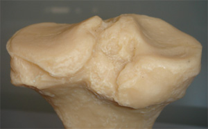
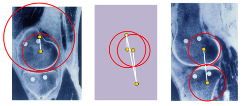
Sagittal sections through a TFJ (Nägerl 1993); |
The medial TFJ (figure on the left) of a dissected sample reveals a concave tibial and a convex femoral joint surface. The red circles roughly correspond to the radii of curvature of the respective joint surfaces. The diameters of the circles are clearly different, and the joint is said to be `incongruent´. The center of the circles, indicated in yellow, do not coincide.
The lateral TFJ (figure on the right) has a convex tibial surface, in contrast with the
medial side. As a result, the tibial rotational axis lies distal to the joint surface. The
lateral femoral condyle is convex and the axis lies more posterior in the direction of the medial femoral axis.
|
|
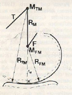
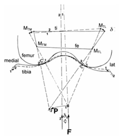
Because the guiding contours can be closely approximated by circles (radii: R FM , R TM), the TFJ structurally represents an overlapping dimeric link chain. The link R M (= R TM - R FM ) equals the distance between the femoral and tibial medial center of curvature (M FM and M TM ). The line R M passes the contact point K and is perpendicular to the articulating surfaces. Therefore, it coincides with the force line of F M. F= femur, T=tibia
|
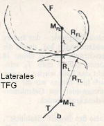
The TFJ structurally represents a stretched dimeric link chain. The link (R L = R FL - R TL) equals the distance between the femoral and tibial center of curvature (M FL and M TL). R L and R M defines the line of force transfer F L, which is perpendicular to the articulating surfaces at the contact point K. The forces, which are perpendicular to the joint surface, act to minimize the shearing forces on the joint surface. |
|
The four centers are tightly coupled via the bones, muscles and ligaments and, in this way, represent what is called a link quadrangle (see figure in the center above). This kind of joint gear system is well-characterized in biomechanics and it is well known that its design uniquely determines the motion path during flexion and extension:
-
-
|
The joint surfaces roll on each other during flexion up to 30 deg.
Starting from 30 deg, sliding becomes appreciable, and beyond 60 deg, it is the main type of motion.
|
|
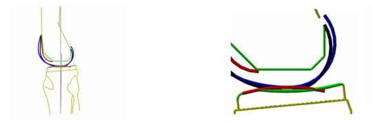
The animation illustrates, in a simplified fashion, the movements of the human knee joint during flexion and extension. The four axes are shown in the figure on the left side. At the outset of flexion the joint surfaces roll on each other. The articulating surfaces are labeled in blue/red (lateral TFJ) and in black/green (medial TFJ). The zoomed-in animation (on the right side) illustrates that the lateral TFJ rolls towards a more distal and posterior position with the medial TFJ trailing along in the process. This behavior is because the axis and joint surface lie more posterior for the lateral femoral than for the medial condyle. As the distal motion of the lateral femoral condyle (relative to the proximally aligned medial tibial joint surface) comes to an end, the knee starts to slide. The transition from rolling to sliding is smooth.
Rolling and sliding involve the eminentia intercondylaris of the tibia and the medial part of the femoral condyles.
What is the purpose of the initial rolling motion?
The rolling motion of the joint surfaces for flexions up to 30 deg has the following
benefits for walking and running:
-
-
-
-
-
-
|
The shearing forces due to static friction, which needs to be overcome at the start of each movement and at the turnaround points, are negligibly small in rolling joints.
Likewise, sliding friction, which otherwise causes wear and tear and generates heat as well as shearing forces, is basically negligible.
In a rolling-type joint, the forces are perpendicular to the joint surface, keeping shearing forces at a minimum.
Therefore, any forces, which would act on the joint surfaces and significantly contribute to wear and tear, are kept at a minimum. As a result the joint can move with little friction and wear and tear even under heavy loads.
Since rolling is a directed and stable type of movement, it helps prevent spontaneous wobbling and instability.
Because of the incessant migration of the contact surface the forces are spread out evenly over a large area of the joint surfaces. |
|
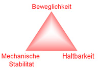
These advantages are the main reasons behind the remarkable stability, mobility and durability of the natural knee. |
|
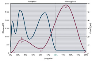
The forces that act on the knee during walking are about three times the magnitude of those associated with a person's weight (Thambyah 2005, Morrison 1970). In view of these large forces, Nature's rolling joint design is a brilliant idea to avoid wear and tear in the first place. |
|
Blue line = load on the knee joint during walking (in N); red line = flexion of the knee joint (in deg). During the resting phase in a walking cycle, the knee is loaded by about threefold of a person's weight
(Thambay 2005, Morrison 1970) |
While the loads associated with physical exercise are not exactly known, it is safe to assume that the peak loads are vastly greater than those during mere walking. Again, the rolling principle plays an important role in attenuating otherwise destructive loads during strenuous physical activity.
These observations are fascinating from an engineering and biological point of view (Nägerl 1993). It is interesting to note that over the course of evolution, the problem of wear and tear was largely overcome by kinematic design rather than by developing more durable tissue materials.
As a consequence of the link quadrangle and its oppositely curved surfaces, the joint cannot be over-stretched. Moreover, the inherent blocking mechanism is not rigid like an end-stop, but rather flexible.
Other degrees of freedom of the knee joint
Abduction/adduction and axial rotation are made possible by the fact that the contact surfaces of the TFJ are right next to the eminentia intercondylaris , as opposed to the lower regions of the tibial surfaces. In fact, abduction/adduction is made possible by an additional link quadrangle (see figure below). As a result, the joint becomes more stable when force-locking, associated with a load, restricts the degrees of freedom of the joint. Conversely, their mobility is restored when the load is removed. |
|
Frontal section through the TFJ with a schematic diagram of the link quadrangle
(adduction and initial position)
|
The situation is similar for axial rotation. It can be easily demonstrated in a flexed state when no loads are present. There is a small axial inward rotation during flexion and a
small outward rotation during extension. Under a load, this type of movement is markedly restricted. |
Sensor system for non-stop force-locking
Under force-locking, the surfaces of the TFJ largely determine the kinematic properties of the link quadrangle. In the absence of any load, the force-locking disappears and the kinematics are very different.
The cruciate ligaments fulfill a sensory function by monitoring the status of the force-locking and by controlling the fusimotor system and the tension of the muscles. At the same time, the collateral ligaments and the menisci play an important role in regulating muscle tone. This reflex system ensures that the joint surfaces remain in contact at all times, and that the kinematics of the link quadrangle apply. |
|
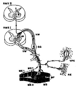
Schematic representation of the basic neuronal network of the somato-sensory (Vater-Pacini bodies VPB and Ruffini end bodies RE of the cruciate ligaments and muscle spindles MS of the muscles) and somato-motor fibers innervating the motor endplate ME1 of the skeletal muscles (alpha-motor neuron) and the motor endplates ME2 of the muscle spindles (gamma-motor neuron). Cross sections through the spinal cord; left spinal nerve, anterior root (AR) and posterior root (HR). Arrows indicate the direction of nerve conduction. SCS 1, SCS 2 = spinal cord segments, SG: spinal ganglion that house the cell bodies of the somoto-sensory fibers, IN = interneuron, that completes the polysynaptic reflex arc.
MF = muscle fibers of the musculature.
|
|
|